


The Build – Part 7
The Team C TM4’s front suspension is pretty standard, however it uses inserts in the arm mounts to adjust kickup and roll centers. It also features adjustable droop, however these screws are impossible to get to once the suspension is installed. Keep this in mind during the build.
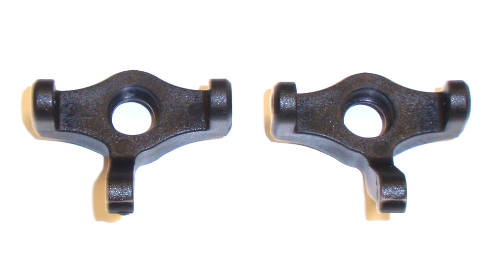
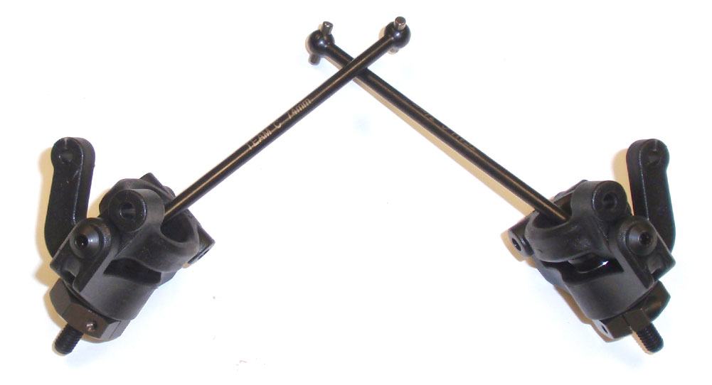
Shown here are the left and right steering blocks. Pay close attention to these during the build; they are not interchangeable and, even though the manual shows markings denoting the left and right, mine didn’t. So yes, it is possible to assemble them on the wrong side. The one on the left is the left side; the one on the right the right side.
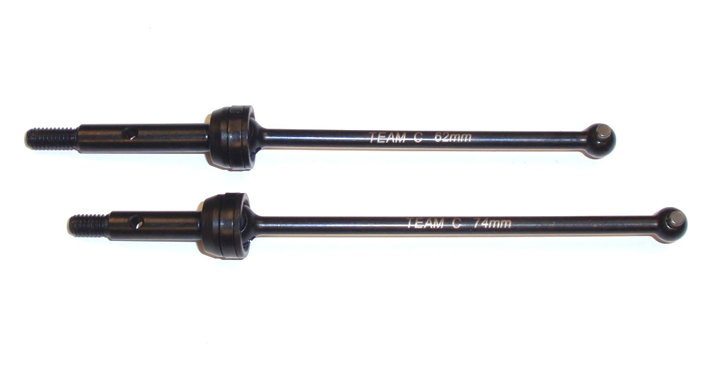
The TM4 comes with pre-assembled front and rear CVDs as well. The top one (62mm) is the rear bone, the bottom one (74mm) is the front bone.
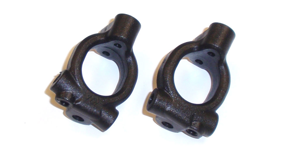
The caster blocks are also different. They are, fortunately, marked with a 10L and 10R, indicating a 10° Left block and a 10° Right block.
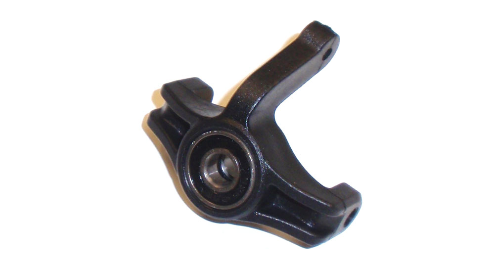
Assemble the steering blocks by pressing a 5×10 and 5×13 bearing into each.
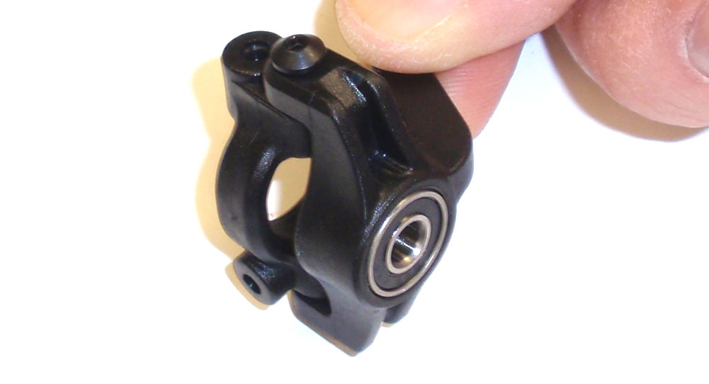
Attach the 10L caster block to the left steering block and the 10R caster block to the right steering block.
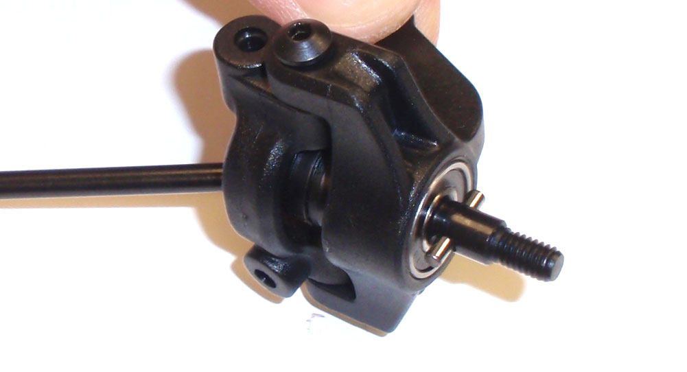
Slide a 74mm front CVD through the assembly and capture with the wheel pin.
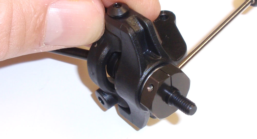
Slide the wheel hex over the pin and pinch it closed by tightening the M2x5 screw.
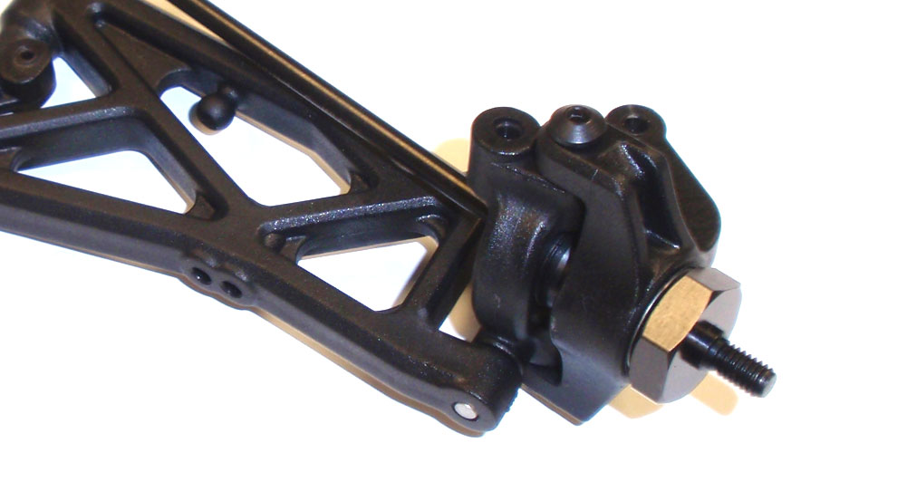
Your front steering blocks should look like this.
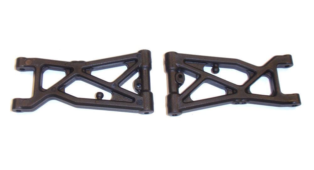
Check out the front suspension arms. The arm on the left is facing the right way (if the front of the car was facing up). The one on the right is incorrect. Using the one on the left as the guide, install a 3×10 setscrew into the droop hole. Yes, the manual states a 3x8mm, however the 3×10’s are used when building the anti-roll bar links and were a bit too long. The 3×10’s work better here for droop adjustment. Screw them in so an equal amount of thread is sticking out both sides of the arm. This is a good initial setting.
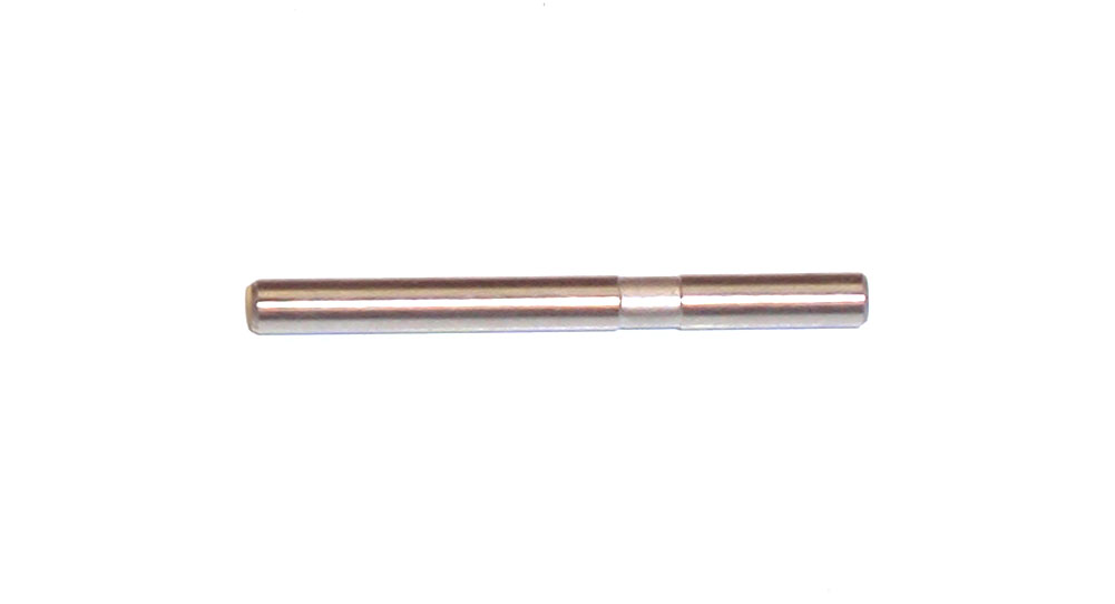
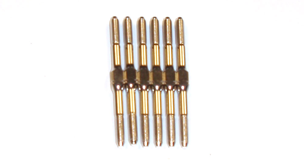
This is the outer hinge pin. Notice the groove in it. This is where a setscrew will seat to capture the hinge pin. Keep this in mind in the next step.
Slide the hinge pin through the suspension arm and steering assembly. Note the direction of the hinge pin in the manual.
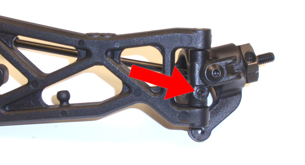
The arrow shows where the M3x3 setscrew will enter to secure the hinge pin. Do not overtigthen!
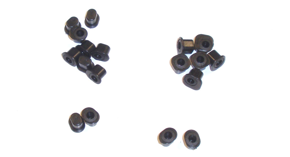
As I mentioned before, the TM4 uses arm mount inserts for adjustment. The manual build has us using 0° inserts for both the FF and FR arm mounts. Grab 4 of these inserts.
Press 2 of the 0° inserts into the FR arm mount.
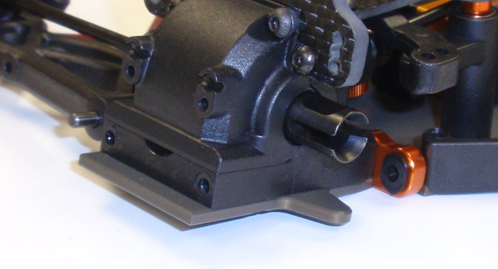
Slide the long, inner hinge pin through the arm and into the FR insert.
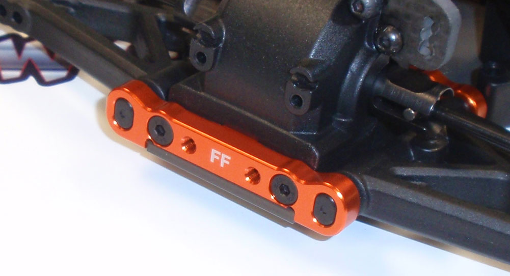
Press 2 more 0° inserts into the FF arm mount and key them to the front of the hinge pins. Secure with the pair of the M3x12 screws.
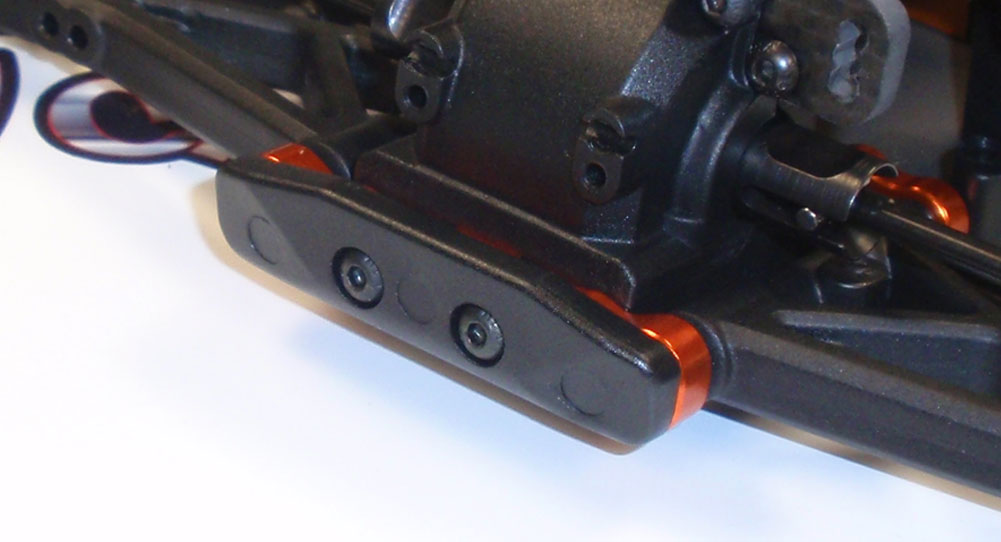
Attach the front bumper.
The TM4 comes with 6 of the same length turnbuckles. Yay.
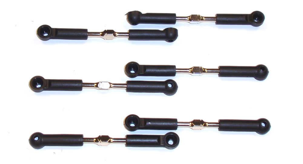
Build 6 turnbuckles; 2 steering, 2 front camber and 2 rear camber. Make sure you keep them separated.
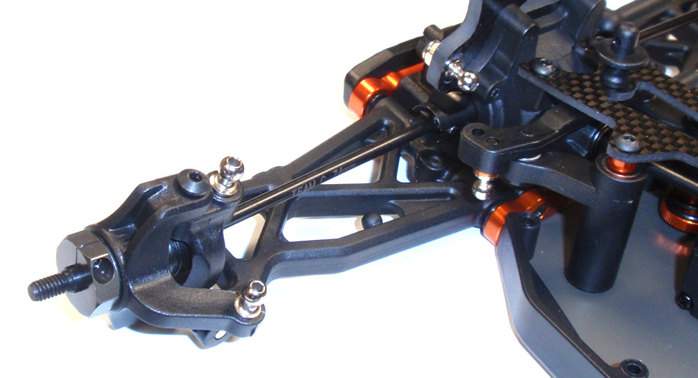
Install a short ballstud into the steering arm and a long ballstud into the steering rack, caster block and front shock tower (using the middle hole in the tower).

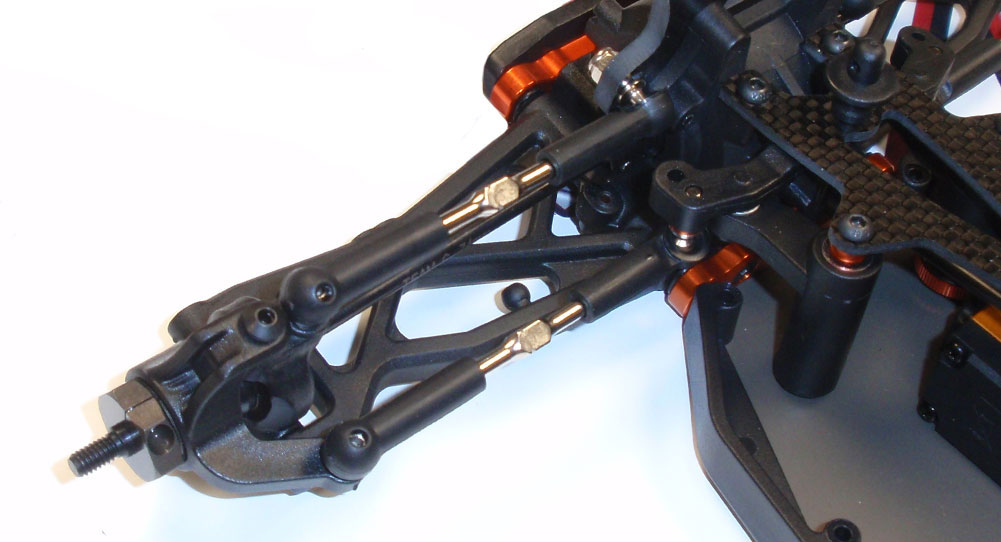
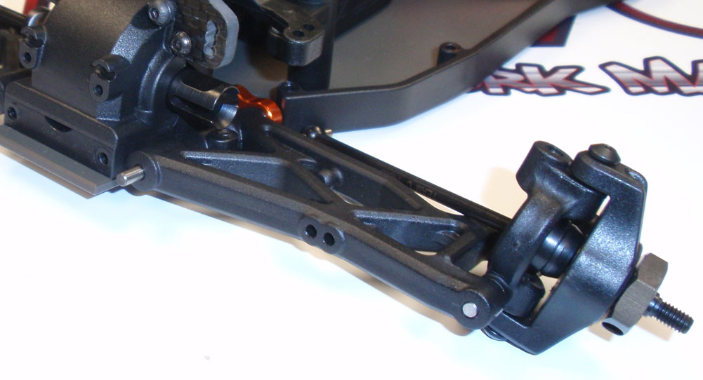
Key the front CVDs to the diff outdrives and pop the steering and front caster turnbuckles into place.
Front suspension complete. Make sure the front arm flop up and down easily without any binding.


