


The Build – Part 8
We just finished assembling the front suspension, now it’s time to move on to the rear suspension.
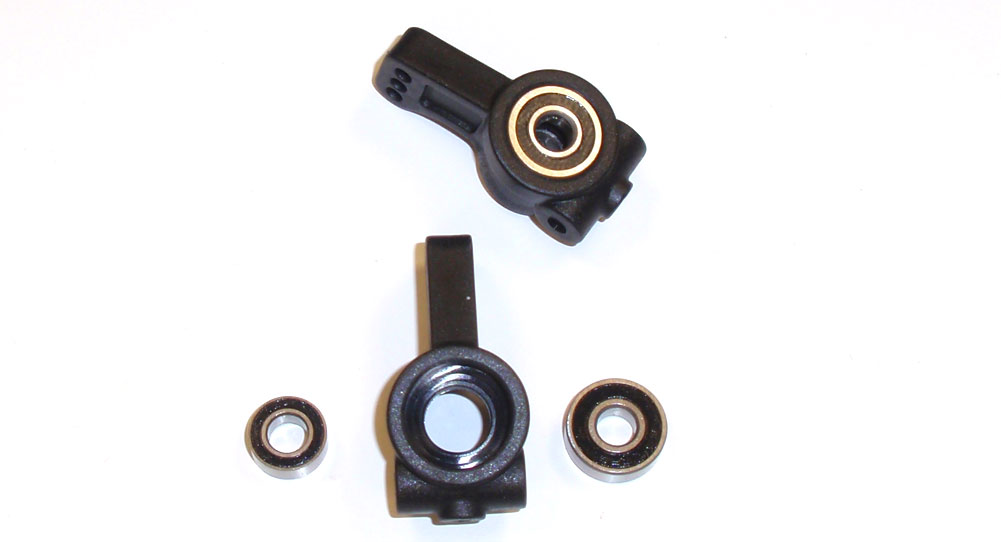
Let’s start by pressing a 5×13 and a 5×10 bearing into each rear hub. The hubs are the same so it doesn’t matter which side they go on.
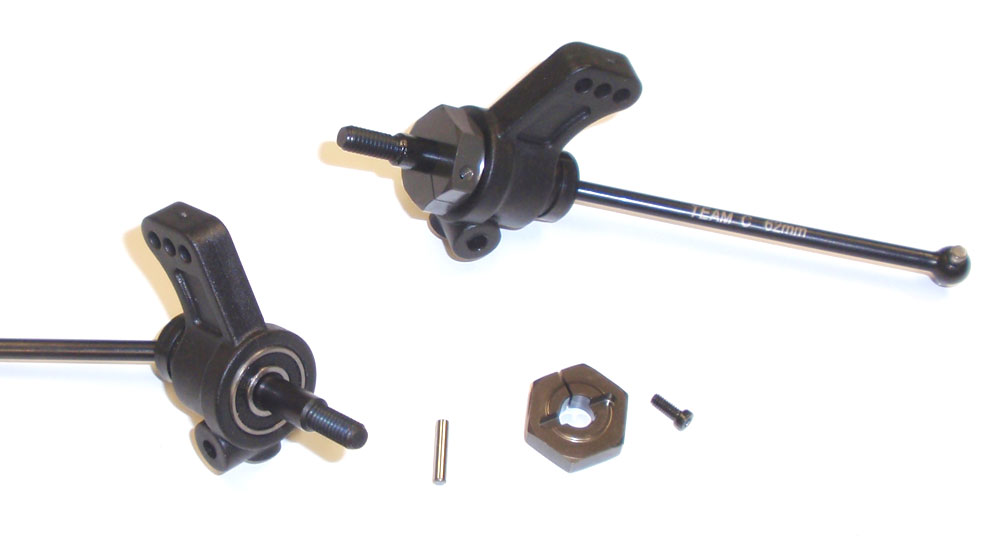
Take your pre-assembled, 62mm axles and slide them through the rear hubs. Add the axle pin followed by the wheel hex. Pinch the wheel hex to the axle with the M2x5 screw.
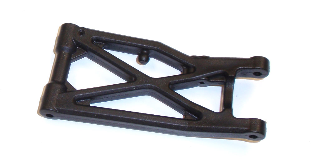
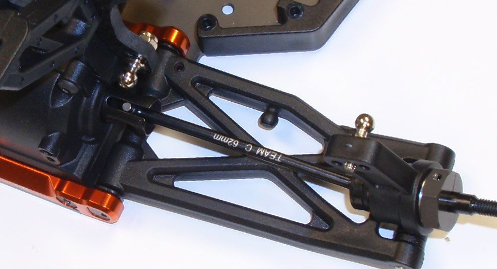
You’ll see the rear arms are ‘gull-winged’, so they’ll only attach in one direction. Take a 3x10mm setscrew from the anti-roll bar bag and insert it into the droop hole (similar fashion as the front arms). Drop the 3x8mm setscrews we were going to use here in the anti-roll bar bag.
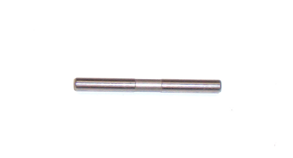
Find the rear, outer hinge pins. You’ll see the same recess in these that were in the front ones, just a little different positioning.
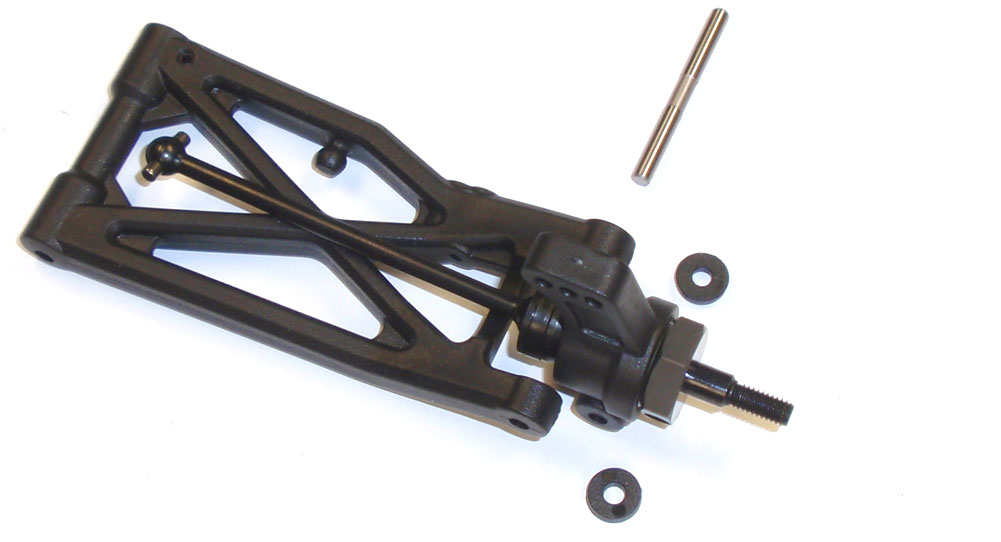
Slide the hinge pin through the rear suspension arm, a wheelbase shim, the rear hub and a second wheelbase shim. This is the standard wheelbase setting for the TM4. Flip the arm over and insert a M3x3 setscrew into the hole to capture the hinge pin. Do not overtighten.
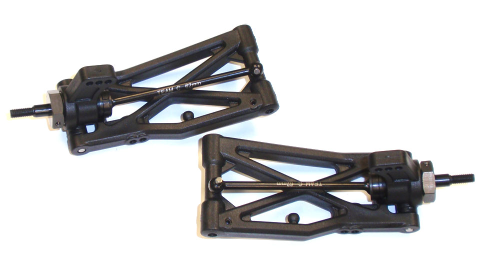
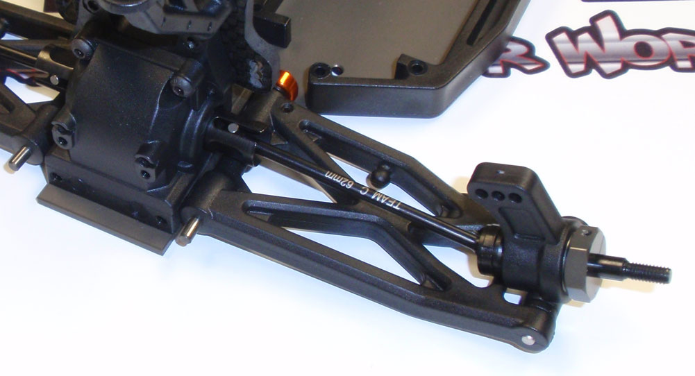
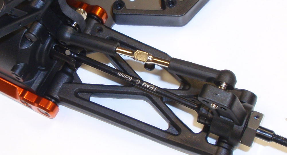
Here is what you pair of assembled rear suspension arms should look like.
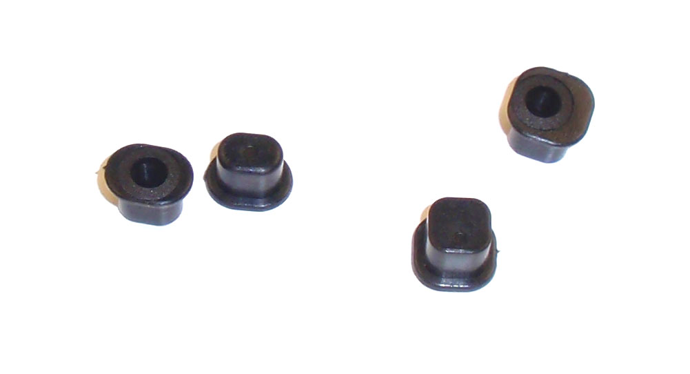
Like the front, the rear arm mounts use inserts to control anti-squat, roll center and rear toe. Grab a 0° round insert and a 1° square insert.
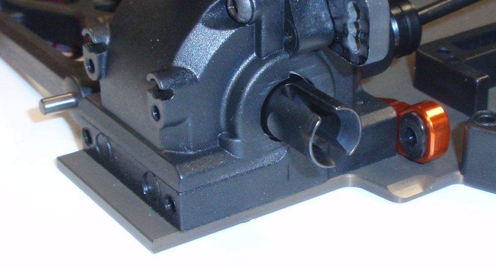
Press the 0° inserts into the RF arm mount.
Slide the long, inner hinge pin through the suspension arm and into the 0° arm mount. Note the direction of the suspension arm; the shock mounting holes face the front of the car.
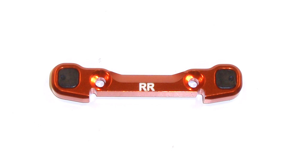
Press the 1° square inserts into the RR arm mount, making sure the single ‘pip’ is towards the outside.
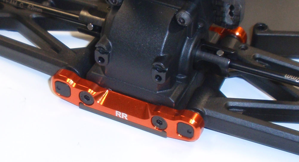
Slide the RR arm mount over the rear hinge pins and screw into place.
Insert a long ball stud in the middle hole in the rear hub and the middle hole in the shock tower.
Key the CVD to the outdrive and pop the rear camber links you’ve already built onto the TM4.
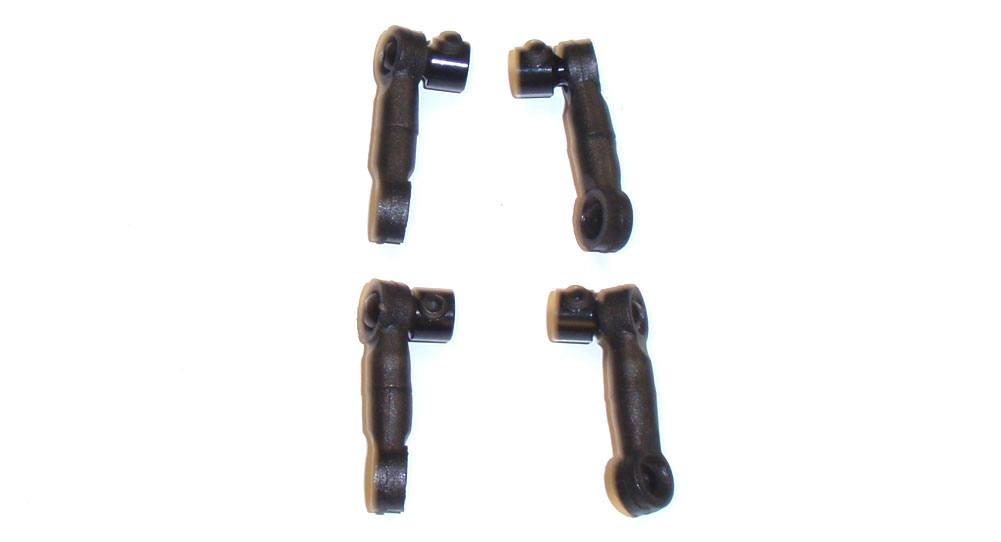
Build 4 anti-roll bar links. You will be using the 4 M3x8 setscrews that used to be the droop screws. You’ll see they work much better here.
Pop the anti-roll bar links onto the balls on the front suspension arms. I’ve popped the front camber link off so you can see the attachment point better. It’s not necessary to do this to connect it. Note which direction the aluminum ballstud is facing.
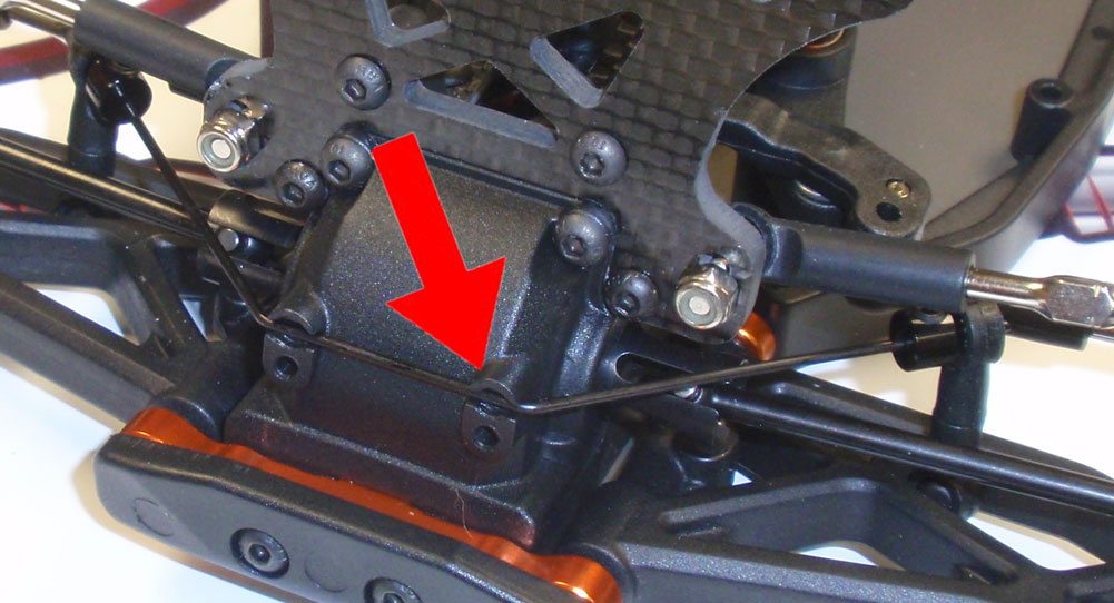
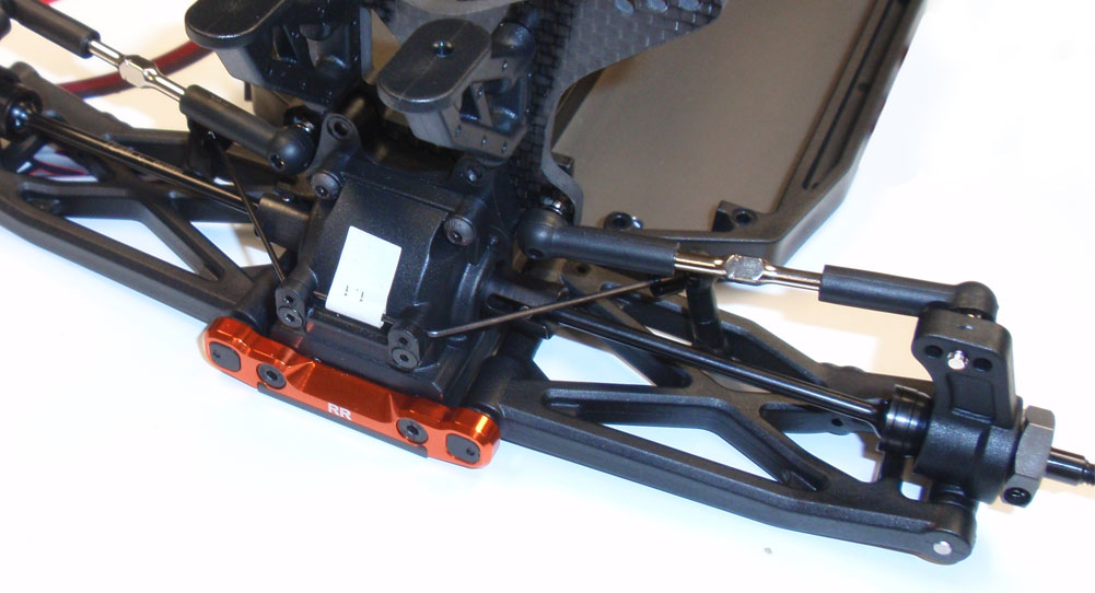
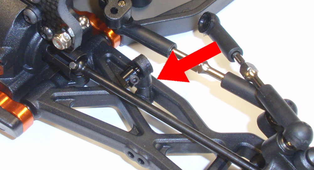
Slide the 1.2mm anti-roll bar into the links and secure with the M3x3 setscrew. Set the anti-roll bara into the groove (notated by the arrow).
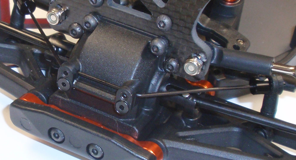
Attach the anti-roll bar cover. Insert and tighten down the pair of M3x3 setscrews into the cover, only enough to barely make contact with the bar. You don’t want to pinch the bar, only remove the forward/backward play.
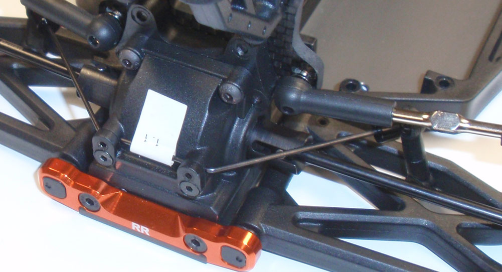
Using the same method as the front, attach the rear anti-roll bar. You’ll notice a tag on mine that says 1.1. This is different than the manual which states a 1.2mm bar. The 1.1 could go on the front or rear, I’m starting off with it on the rear.
Suspension complete. Time to build and bolt up the shocks!


