Brushed motors are great to get you in the door for cheap, and if you’ve never driven a hobby grade RC before then they have more than enough speed and power for the first time driver, but once you get the hang of driving, you’re going to want more power. Or maybe you’ve just worn that old brushed motor out and it doesn’t perform as well as it used to, either way you’re going to eventually want to upgrade to a brushless system for the speed, power, efficiency, and because they require very little maintenance. It is actually not that difficult, and with systems like this one from RC Gear Shop, not all that expensive either. So I am going to walk you through the install, so you can see just how easy it is. I will be performing this on the Arrma Granite, but much of this information will apply to many 1/10 2WD off-road RC machines.
ITEMS USED • RC Gear Shop 1/10 3900Kv motor w/ 80A ESC RGZC3339 $82.99 • Arrma Granite ARAD37 $159.96
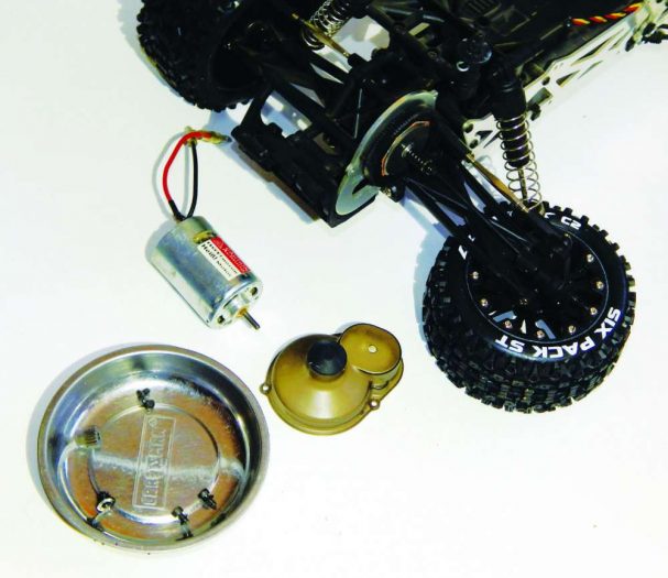
1 Start by removing the rear wheel and spur gear cover. I keep all my screws and nuts in a magnetic bowl so they don’t get lost. I then remove the pinion gear before removing the two screws that hold the motor in. I unplug the motor and remove it from the vehicle.
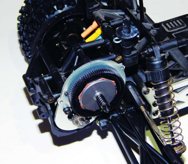
2 Put the new motor in so the wires are pointing up, so they are less likely to take hits. I also position them toward the front, so that they are as close as possible to the ESC and I can keep my wires shorter.
3 Once the motor is positioned facing up, I need to line up the holes to the slots, but first I like to get the screw ready on my hex driver, that way I can be holding the motor in position with one hand and only need the other hand to grab the driver with the screw on it and put the screw in. Refer to your car’s manual to figure out the proper gearing for this motor. I am also switching to smaller tires so I guesstimated that a 20-tooth would put me in the range. At this point the motor screws are loose enough I can slide the motor back and forth.
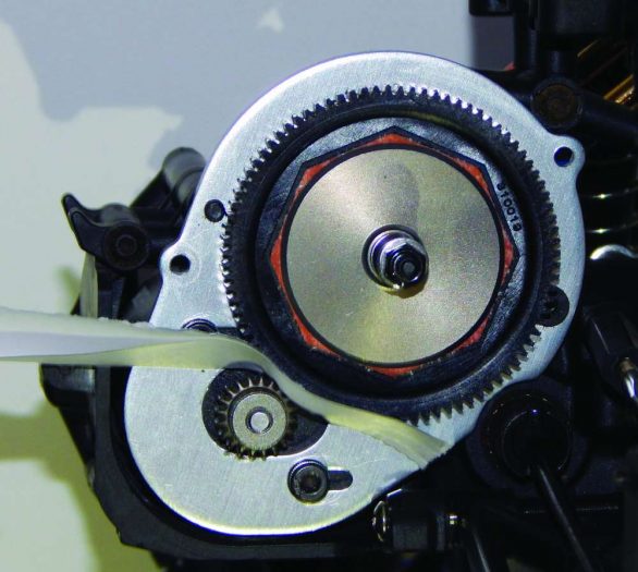
4 Now it is time to set the gear mesh. There should be a little wiggle room between the teeth. If the mesh is too tight it will create drag that will melt your spur or overheat your motor. I’ve become pretty good at eyeballing the gear mesh, but for many years it was difficult for me, and I relied on the old folded piece of paper trick. Just smash the paper between the gears, and then tighten down your motor screws. Make sure all your screws are good and snug as they have a habit of working them- selves loose in this area. Replace the cover and wheel, and the motor installation is buttoned up.
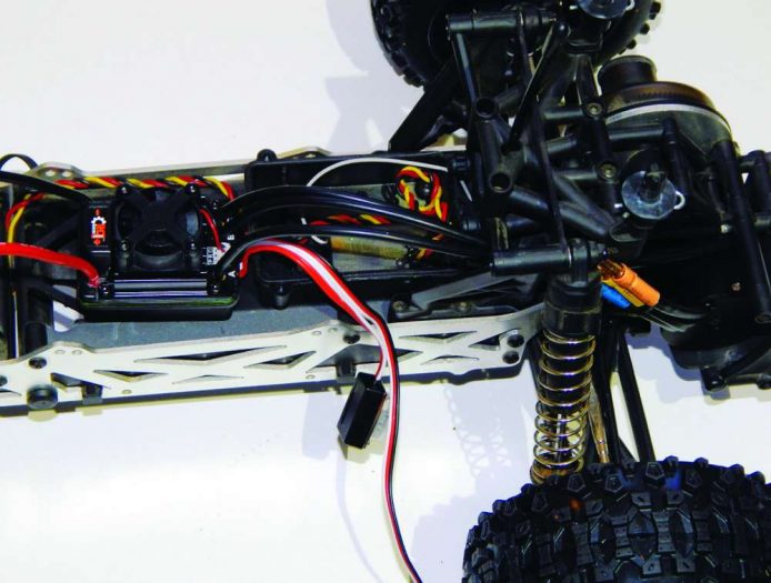
5 Now it’s time for the ESC. Gently pry the old ESC off, and unplug it from the receiver. I’m not going to attach the ESC just yet. I am only mocking it up so I can see how long to make my wires. Shorter wires will look cleaner and be slightly more efficient. I pull them past the plug on the motor wire and cut the wire about a half inch past the end of the plug. Leave a little slack so they don’t come unplugged during crashes.
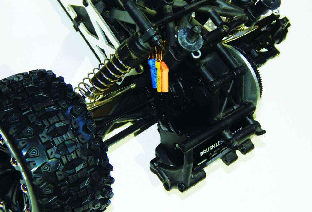
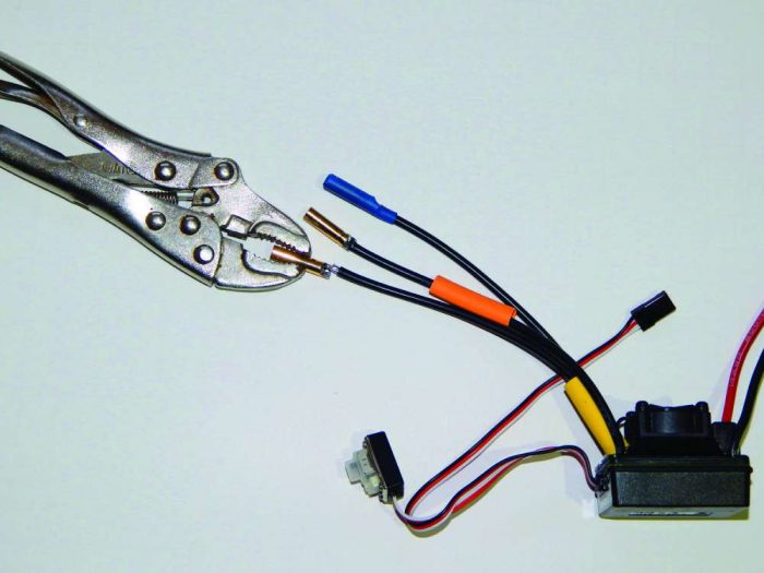
6 This ESC will require you to solder the plugs on. That’s fine with me as I like to shorten my wires and I feel soldering is an essential skill in this hobby. A 35-40 watt iron and some 60/40 rosin core solder will work fine for this task. I use a small pair of vise grips to hold the plug in place. To tin the plugs, I heat the plug with my iron and touch the solder to the plug right next to the tip of the iron, until the solder runs smooth and shiny. I do the same for the tips of the wires and then smash the wire to the plug with the tip of my iron until the solder runs smooth of both surfaces. I cover the plugs with the provided heat shrink. I guessed at the color coding and got lucky with blue being “A” on the ESC, and red being “C” on the ESC.
7 You will also need to install the battery plug on this ESC, which is also great with me because I always swap my battery plugs for Dean’s plugs. I soldered the plug on the same way as I did the motor plugs, but make sure you put your heat shrink on first. Be super cautious to observe polarity here, as if you hook your battery up back- wards, you will fry your ESC and battery. Double, even triple check your work.
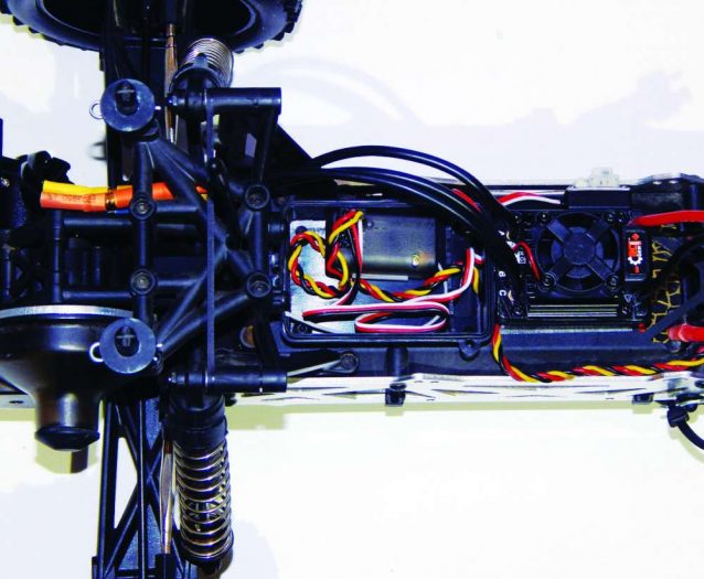
8 Before attaching the ESC you will want to prep both surfaces by removing the oils with a solvent such as denatured alcohol or Naptha. I find window cleaner with ammonia works fine. I needed to run the ESC wires into the receiver box before attaching it, and then I stuck the included piece of double sided tape to the deck of the car before positioning the ESC and pressing down. You will also need to find a place for the On/Off switch. I found that the side of the ESC was the best position in my circumstance. I then plugged the ESC into the receiver and motor wires.
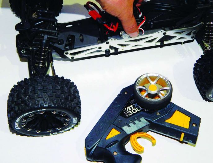
9 Everything is installed but it is not quite ready to rock. First I will need to calibrate the radio. To do this I first turn on my transmitter, then plug in my battery, but before I turn it on, I hold down the button on the switch. It started beeping. I let go of the button, pressed again with the radio in neutral, one beep, press again while holding full throttle, two beeps, hold full reverse, three beeps, and it should be ready to go after three seconds, but no, denied. I started to panic, but I turned it off and back on again, and all was fine. I took it out for a rip, and it was like a whole new toy. Time for fun!